Flow Between Two Reservoirs
Dept of Civil Engineering
University of Texas at Austin
Prepared by Ferdinand Hellweger, David R. Maidment,and Brian Adams
Table of Contents
Java Applets are small programs that can present a physical situation
and let you manipulate the components of that situation so as to see
the effect on its behavior. In this case, a fluid flow system between
two reservoirs is presented in an applet called
Visiflow, and the user has a number of options about
the connection between the reservoirs, including changing pipe diameters,
installing pumps, changing the level of the water in the two reservoirs,
adding valves and turbines, and changing the pipe roughness. Once a
particular configuration is chosen, the user can execute the solution
and update the flow through the system and the hydraulic and energy
grade lines between the two reservoirs.
- To provide understanding of flow in pipes with pumps, head losses
and pipe fittings.
- To provide experience with the Visiflow Applet
- To present a simple design example so that the user can determine
the configuration of components necessary to achieve a desired flow
between the reservoirs.
This exercise can be executed on any computer running a world wide
web browser which is capable of executing Java Applets (Netscape 2.0 or
higher). It does not require an external data file. Get the Applet
by clicking on:
The web address for this applet is:
http://www.ce.utexas.edu/gishydro/ferdi/webedu/visiflow/visiflow.html
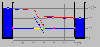
When you first load the Visiflow Applet, you will be presented with
a view that looks like this. If you don't get any picture of the
two reservoirs, this means that you don't have a web browser capable
of viewing Java Applets or possibly that your computer system is located
within a security system which does not allow entry of Java Applets
from outside the local network.
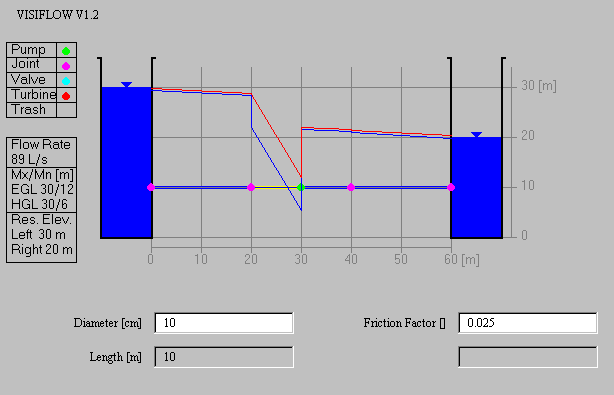
The reservoirs are located 60m apart and have water levels which can
be altered from 0 to 30m elevation on either side.
(a) The Data Box
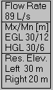
The flow system shown has two reservoirs whose elevations are shown at the
bottom of the Data Box, the left reservoir being at
30m and the right reservoir at 20m. These levels can be changed by
clicking on the reservoir surface and dragging them up and down. As you
do so, you'll see the discharge between the two reservoirs alter. Initially,
the discharge is 89 liters per second. If you lower the left reservoir level the
discharge goes down; if you raise it, the discharge goes up. And
conversely for the right reservoir. The red line in the diagram is
the EGL or Energy Grade Line, which measures the total head of the
system at any point, and the blue line beneath it is the HGL or
Hydraulic Grade Line, which measures the pressure and elevation head
at each point. The maximum and minimum elevations of these lines
are shown in the center of the data box, initially as EGL 30/12 and HGL
30/6, indicating that in the left reservoir, the
Energy and Hydraulic Grade lines are both at the water surface elevation (30m),
and then they decline as energy losses consume head to minimum values of
12 for the EGL and 6 for the HGL, respectively, in this initial example.
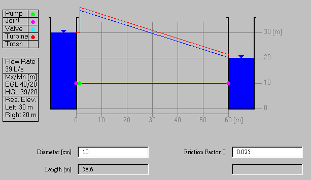
(b) The Pipes

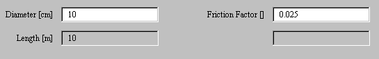
If you click on a pipe, you'll see it highlighted in yellow and its parameters
shown in the boxes below the diagram. The pipe initially highlighted has a
diameter of 10 cm, a length of 10m and a Darcy-Wiesbach friction factor
of 0.025. The values in the clear boxes can be altered by the user (diameter
and friction factor), while the value in the grey box is determined by
the system from the diagram. If you click on other pipes, you can read
off their diameter, length and friction factor. Strictly speaking,
the friction factor is a function of the velocity and discharge through
the pipe, but it is here set to a fixed value to simplify the calculations.
(c)The Fittings

There are four kinds of fittings that can be inserted into the system:
a pump, joint, valve, and a turbine. You can insert a fitting by clicking
on it and dragging it into position on the pipe system. You remove a fitting
by dragging it and putting it into the trash box at the bottom of the
fittings list. The applet will adjust the lengths of the pipes between
the fittings automatically.
Pumps and Turbines 
A pump or a turbine characterized by its
head alone. In a more complete analysis of this system, the pump or
turbine head would vary
according to the discharge through the system but it is here held fixed
to simplify the calculations. Pumps supply head to the system, turbines
remove it.
Joints and Valves 
A joint is characterized by a loss coefficient which is the factor K
multiplying the velocity head at that location to give
the minor loss associated with the joint between two pipes, or at the
entrance or exit to the pipe system. A valve is likewise characterised by
a loss coefficient applied to the velocity head. This coefficient can be
changed by the user to values of perhaps 1 or 10 or 100 or 1000 representing
differing degrees of loss of head as the flow passes through the valve.
Ok, you're ready to run the Applet now!
(a) Flow without pumps or minor losses
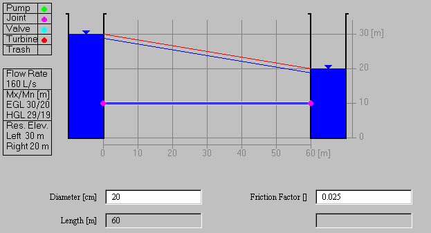
Lets simplify the system by deleting all the fittings between the
reservoirs, and setting the head loss coefficients at the entrance
and the exit to 0. Get rid of the pump and the two junctions located
on the pipe between the reservoirs by dragging them to the trash box.
The screen flickers a bit when you do this but that is because it
refreshes itself while you are doing the drag operation. Click on
the junction at the entrance and exit and set the loss coefficients
to 0 (the default value is 0.5). The only head loss is now the
friction loss
in the 60m of 20 pipe between the reservoirs. In this situation,
the discharge can be found by writing the energy equation between
the surfaces of the two reservoirs as:
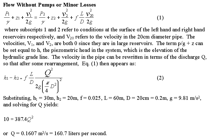
The value of 160.7 liters per second determined from this computation
is the essentially the same as that found in the data box of the Visiflow Applet for
these conditions, except that the value shown in the data box is only
the integer part of the discharge.
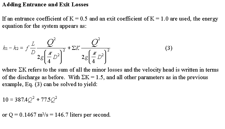
(b) Adding Entrance and Exit Losses
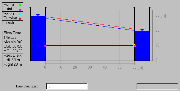
Click on the entrance junction and set the loss coefficient
equal to 0.5 (a square-edged entrance)
and on the exit junction and set the loss coefficient
equal to 1.0 (the velocity head is dissapated as the flow discharges
into the outlet reservoir). The flow drops to 146 liters per second
to reflect the additional losses. Notice how the energy grade line
now drops below the level of reservoir 1 as the flow enters the
pipe and the hydraulic grade line on the reservoir 2 runs right
into the water surface, indicating that the velocity head is all
dissapated as the flow discharges into reservoir 2. The computations
can be checked by the following procedure.
(c) Changing the Reservoir Levels

Drag the level of the left reservoir down to 20m and raise the level
of the right reservoir to 30m. Click on the entrance and exit junctions
and set the values to 0.5 and 1.0, respectively. Here is the same
flow system that you just analyzed with the flow going in the opposite
direction. You may find that the flow doesn't quite come out to
146 liters per second and if so, make some minor adjustments to the
reservoir levels so that the results come out ok.
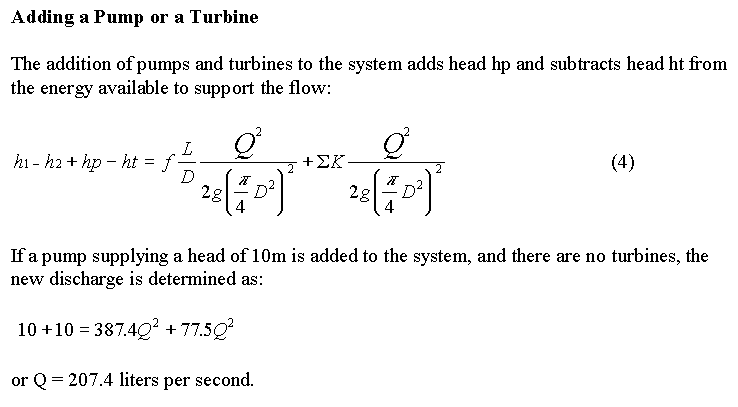
(d) Adding a Pump
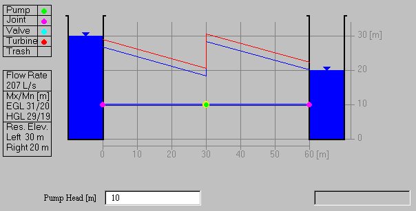
Add a pump with a head of 10m by dragging a pump symbol from the Fittings
Box and drop it near the center of the pipe. the discharge is increased to 207 liters
per second and the hydraulic and energy grade lines reflect the increase
in head at the pump. The discharge computation can be verified as follows.
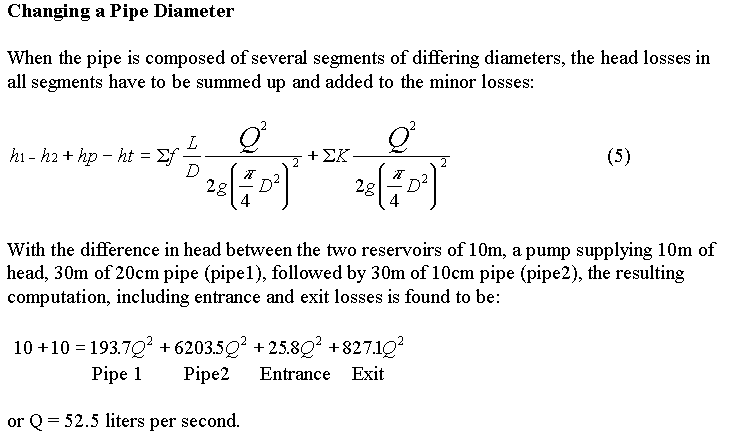
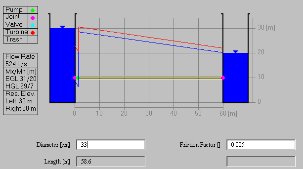
(e) Changing the Pipe Diameter
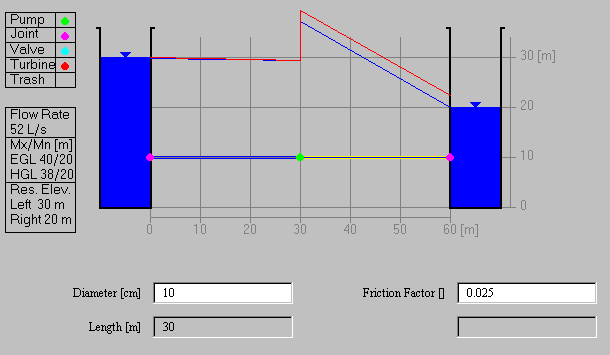
Suppose now that we change the diameter of the pipe to the right of the
pump from 20cm to 10cm. The resulting discharge drops to 52 liters per
second, reflecting the high energy losses in the smaller pipe. The
entrance and exit losses now have to be calculated with the corresponding
velocities, that is, the velocity in the 20cm pipe for the entrance
loss and the velocity in the 10 cm pipe for the exit loss. Notice how
there is relatively little head lost in the 20cm pipe and nearly all
the energy is dissapated in the 10cm pipe. This occurs because
as shown by Eq. (3), the head losses are inversely proportional to the
fifth power of the diameter for friction losses in pipes, and inversely
proportional to the fourth power of the diameter for minor losses.
(f) Adding a Valve
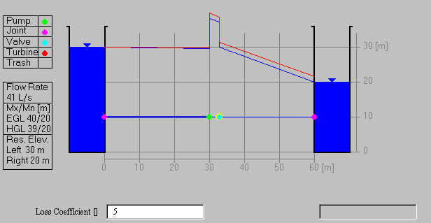 Valves are added on the outlet side of pumps to control the flow. Here
a valve with a loss coefficient of 5 velocity heads reduces the flow
from 52 liters per second to 41 liters per second. The calculations can
be verified in the same manner as that used previously, by adding the
minor loss in the valve to the losses on the right hand side of the energy
equation.
Valves are added on the outlet side of pumps to control the flow. Here
a valve with a loss coefficient of 5 velocity heads reduces the flow
from 52 liters per second to 41 liters per second. The calculations can
be verified in the same manner as that used previously, by adding the
minor loss in the valve to the losses on the right hand side of the energy
equation.
Ok! Now you are ready to design a pump and pipe system!!
(a) Pump and Valve
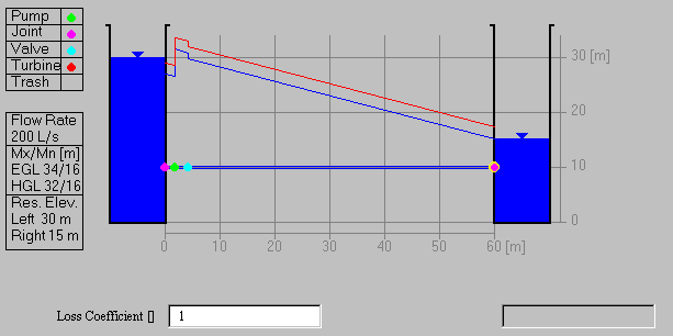
Design a pump and pipe system which will convey 200 liters per second
of water between two reservoirs whose difference in elevation is
15m using 20cm pipe having a loss coefficient of 0.025. What pump
head should be used? If a valve is installed on the outlet side of
the pump to control the flow, what loss coefficient should the valve
have? What is the power imparted to the flow by the pump (Kw). Note
that you need to drag the elevation of the right hand reservoir down
to 15m to achieve a 15m difference in elevation between the two
reservoirs.
To be turned in: the value of the pump head and valve loss coefficient
needed to have a flow of 200 liters per second. Verify the results
of the applet calculation by determining the discharge by hand using
the methods shown in the previous examples. What power in kW is supplied
to the fluid by the pump?
(b) Relationship between Pipe Diameter and Discharge
Reload the applet so that the levels are restored to
30m on the left hand side, and 20m on the right hand side.
Install a pump supplying 10m of head at the beginning of the pipe,
and change the diameter of the pipe in increments of 5cm beginning
at 5cm and ending at 30cm diameter. Note the discharge in the
pipe for each diameter.
To be turned in: a graph relating the discharge to the pipe
diameter.
(c) Cavitation
Cavitation in pumps occurs when the pressure on the inlet side
of the pump falls too low. In this case, a negative pressure
head of about 7m is the safe maximum for preventing cavitation.
For the conditions in Problem 2, determine what the maximum
pipe diameter and discharge through the pump that can occur
without inducing pump cavitation. The elevation of the pump
is 10m and the negative pressure head on the pump is measured
by the difference between the pump elevation (z) and the
minimum elevation of the hydraulic grade line (p/gamma = z - h). In
the example shown above, the minimum piezometric head is h = 7m, so
the negative pressure head on the inlet side of the pump is
p/gamma = 7-10 = -3m. This corresponds to a suction pressure of
p = -3 * 9.81 kPa = 29.4 kPa or about 1/3 of an atmosphere.
To be turned in: the limiting pipe diameter for cavitation. What
is the inlet pressure at the pump for this flow condition?
Develop a pump and pipeline design that addresses a particular
set of physical conditions of your own devising.
To be turned in: a brief description of your pump and pipe design.
Draw a diagram showing the layout of the system, specify the dimensions
of its components. Specify the discharge through the system and
the pump head and power required..
Ok, you're done!
Go to Course Home Page