by Esteban Azagra
Graduate Research Assistant
University of Texas at Austin
Center for Research in Water Resources
Background
A triangulated irregular network data model (TIN) is an efficient way for representing continuous surfaces as a series of linked triangles. Although both grids and tins can be used for surface representation, tins are especially useful for representing surface elevation, subsurface elevation and terrain modeling, specially when the represented surfaces are highly variable and contain discontinuities and breaklines.
A tin is formed by nodes, triangles and edges. Nodes are locations defined by x, y and z values from which a tin is constructed. Triangles are formed by connecting each node with its neighbors according to the Delaunay criterion: all sample points are connected with their two nearest neighbors to form triangles (by using this method the triangles are as equi-angular as possible, any point on the surface is as close as possible to a node, and the triangulation results independent of the order the points are processed). Edges are the sides of triangles.
Tins are generated from points, polygons and lines. Points used in defining the tin are called mass points. Areas of constant elevation, such as water surfaces are called exclusion polygons. Finally, lines such as streams and shorelines are called breaklines. Breaklines can be either hard or soft. Hard features are things like roads, streams, and shorelines which indicate a significant break in slope. Soft features are things like ridgelines on rolling hills. Ridges like these do not represent distinct breaks in slope but since they separate watersheds you might like to maintain in the triangulation. When a tin is created, mass points become nodes of triangles, while breaklines and exclusion polygon boundaries become triangle edges.
Data sources
Points, polygons and lines can be stored in different formats that can be used to create a tin. Multiple input sources include point, line and polygon coverages; points and breaklines in x, y, z GENERATE input files; and breaklines with z values interpolated from a lattice. This paper focuses on the generation of tins from GENERATE input files.
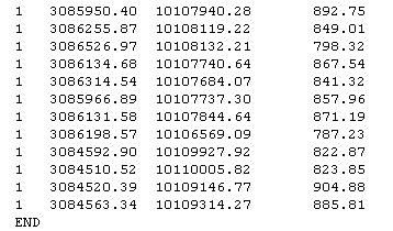
A GENERATE input file is an ASCII operating system file containing x, y coordinates and z values for point or line features. It can be created with the ArcInfo command GENERATE.
Each GENERATE input file must contain a single class of features, either POINT (the file contains points) or LINE (the file contains lines, polygons, or both). Following tables show how both types of GENERATE files look like.
- GENERATE file with point features:
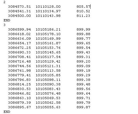
- GENERATE file with lines features.
A numeric item in the file specifies how each feature defined will contribute to the tin. Normally, the codes used are those defined by default when the file is created with ArcInfo. However, as you will see later, different codes can be defined.
The default feature type codes are:
| IGNORE | 0 |
| MASS | 1 |
| SOFTLINE | 2 |
| HARDLINE | 3 |
| SOFTREPLACE | 4 |
| HARDREPLACE | 5 |
| SOFTCLIP | 6 |
| HARDCLIP | 7 |
| SOFTERASE | 8 |
| HARDERASE | 9 |
| BARRIER | 10 |
The following procedures explain how to create a tin using ArcInfo or ArcView.
Procedure
ArcInfo
Follow the instructions shown below:
Arc: w <working space where the GENERATE files are
located>
Arc: createtin <desired TIN name>
Createtin: generate <name of the file with
the points> point
Createtin: generate <name of the file with
the breaklines> lines
Createtin: end
This example assumes that each feature contributes to the tin according to the feature type information established by default. In case different surface feature type codes were used, the user can specify the source of the surface feature type information using the {sftype_item | sftype} argument of the GENERATE subcommand.
Note that the CREATETIN command used here is a versatile tool that creates a tin surface model from multiple input sources including ARC/INFO coverages, ASCII files containing x, y, z coordinates, and breaklines interpolated from a lattice. It also allows you to introduce tolerance values to eliminate duplicate points, as well as factors to change the elevation units when the tin is generated. More information can be found in the on-line help provided by ArcInfo.
In case you have to create multiple tins, you can use the AML code located at Tin - AML Code. The code generates each tin from a couple of files, one corresponding to the points and the other with the breaklines information. For each tin, the points file must be called *p.atn while the lines file has to be called *l.atn (for instance, cover01l.atn and cover01p.atn, cover02l.atn and cover02p.atn, and so on). You can either rename your source files to fit this requirement or modify the AML code (this should not be very tough). Run the code with all the files located in your working space by typing:
Arc: &run tingen.aml
ArcView
Creating tin coverages with ArcView requires you have running ArcView version 3.0 or later, with the 3D Analyst extension. This extension extends ArcView to support surface modeling and 3D visualization.
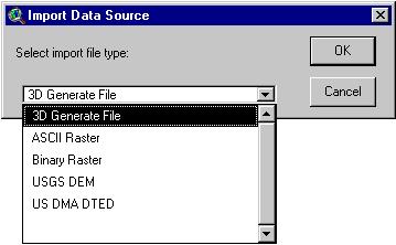
The first step is importing the data stored in the GENERATE files. Use File/Import Data Source... and choose the 3D Generate File from the menu. Notice that ArcView allows importing data stored in different formats. Click OK to confirm your selection.
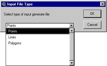
Choose Points as the type of input generate file you are importing and click OK. Select the generate file with the points from your working directory and click OK again. Once you enter the name of the output shapefile you can click OK one more time tostart importing the file. Select Yes to add the shape file generated to the View.
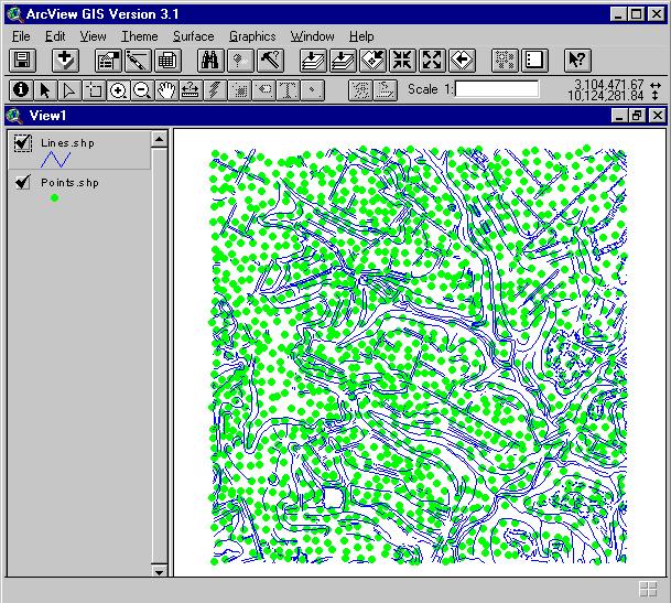
Repeat these steps to select the file with the information corresponding to the breaklines by selecting Lines as the type of input generate file. You should be able to see something similar to this:
The next step is the generation of the tin. With both themes active, select Create TIN from Features... from the Surface menu. The Create new TIN window will appear and the following fields will have to be specified for each active theme.
The Height source field specifies what field, if any, is used to provide height values for the theme. The value <none> can be used for representing features like area boundaries.
The Input as field specifies what surface feature type the theme will be added as. Check that the value selected for the points shapefile is Mass Points, and the one corresponding to the breaklines shapefile is Soft Breaklines or Hard Breaklines, depending on the case. Notice that, if you have both kind of breaklines in the same file, they will be treated either as Soft or Hard Breaklines according to your selection. Thus, it might be necessary to create two different GENERATE files for each kind of breakline. This is not necessary if you use ArcInfo to create the tin.
The Value field specifies what field, if any, is used to provide values for nodes or triangles. If the output type is mass point, the values will be assigned to nodes. If the output type is polygonal, the values will be assigned to triangles. Values are stored with the TIN data model and can be used later for display, query, and modeling purposes.
Click OK and type the name of the tin. After some calculations, a new theme will be added to your view with the tin. It should look similar to this one:
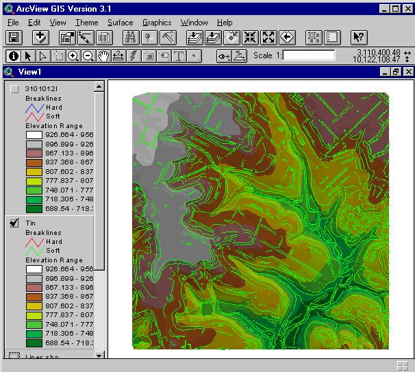
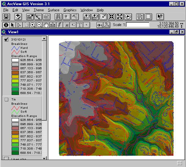
As you can see, all the breaklines in the theme are represented as soft breaklines. This is because both type of breaklines were stored in the same GENERATE file and the corresponding Input as field was specified with a Soft Breaklines value. As stated before, two files would have been required to avoid this problem. The result of processing the same files with ArcInfo is shown below. In this case, you can see how both soft and hard breaklines can be differenced.
Prepared by Esteban Azagra
18 June 1999