Prepared by Sandra Akmansoy and David R. Maidment
with help from Ferdi Hellweger and Cindy How
This exercise is intended to show you how to use AutoCAD to digitize point, line and polygon data layers, how to transform these into Arc/Info coverages, and how to transform the spatial coordinates of these coverages from digitizer coordinates into real world coordinates.
Turn in these answers along with your map and give a brief comment on any difficulties that you had with this exercise.
The Civil Engineering Learning Resources Center (LRC) has a computer with a digitizing tablet set up for digitizing with AutoCAD (Release 12 for DOS). AutoCAD drawing files can be exported into AutoCAD's drawing exchange format (DXF) which can be imported into many other programs including Arc/INFO. AutoCAD is a drawing program that has been around for many, many years and has a very large user base. It is well suited for digitizing.
The easiest way to enter commands when digitizing is by using the keyboard (you can also use the pulldown menus, but that is often not convenient when digitizing). At the bottom of the screen you see a 'Command' prompt. That means AutoCAD is awaiting your instructions.
Carefully tape your map to the digitizing tablet. In order to relate coordinates from the digitizing
tablet to real world coordinates AutoCAD needs you to supply the coordinates of (at least) two points
on your map. This process is called digitizing tablet calibration. If your map is not tied into any
coordinate system you can assign your datum (0,0) at any point and then scale of the two points for
the calibration from there. The best accuracy is achieved when you choose points that are in opposite
corners of the map. Don't take two points on a graphic scale since your accuracy will be poor. For
even greater accuracy use more than two points.
To save your work type "save" at the command prompt, and save your file on a disk.
In our example the map is tied to a coordinate system. We therefore will calibrate according to these four points. This will permit us to reproduce the calibration at a later time if the map has to be removed from the table. Here's the dialog:
Command: tablet
Option (ON/OFF/CAL/CFG): cal
Digitize point #1: (click on the point by aligning the cross hairs of the mouse on the point on your map, and click on the
button labeled 0)
Enter coordinates for point #1: 100,100
Digitize point #2:
Enter coordinates for point #2: 588, 100
Digitize point #3 (or RETURN to end):
Enter coordinates for point #3: 100,338
Digitize point #4 (or RETURN to end):
Enter coordinates for point #4: 588, 338
Digitize point #5 (or RETURN to end):
Command:
The next step is to create some layers. Layers are like transparencies on an overhead projector. You can control whether layers are visible by turning them on or off (putting the transparency on or taking it off the projector). One layer is always the 'current layer'. If you add something to your map it will be added to the current layer (the top transparency). Layers provide a convenient way of organizing your data in AutoCAD, but if you want to transfer your map to Arc/INFO layers become more important than that. Put data you want in separate coverages on separate layers.
In our example we want to produce three coverages (branches, polygon, and nodes), we will therefore create three layers. Invoke the LAYER command and make three new layers named 'branches' 'polygon',and 'poin'. Make the 'branches' layer the current layer and get back to the 'Command' prompt. The dialog looks like this:
Command: layer
?/Make/Set/NEW/ON/OFF/Color/Ltype/Freeze/Thaw/LOck/Unlock: make
New current layer <0>: branches
?/Make/Set/NEW/ON/OFF/Color/Ltype/Freeze/Thaw/LOck/Unlock: color
Color: red
Layer name(s) for color 1 (red)
?/Make/Set/NEW/ON/OFF/Color/Ltype/Freeze/Thaw/LOck/Unlock: make
New current layer
?/Make/Set/NEW/ON/OFF/Color/Ltype/Freeze/Thaw/LOck/Unlock: color
Color: blue
Layer name(s) for color 5 (blue)
?/Make/Set/NEW/ON/OFF/Color/Ltype/Freeze/Thaw/LOck/Unlock: make
New current layer
?/Make/Set/NEW/ON/OFF/Color/Ltype/Freeze/Thaw/LOck/Unlock:
Command:
layer
?/Make/Set/NEW/ON/OFF/Color/Ltype/Freeze/Thaw/LOck/Unlock: make
New current layer <0>: polygon
?/Make/Set/NEW/ON/OFF/Color/Ltype/Freeze/Thaw/LOck/Unlock: color
Color: red
Layer name(s) for color 1 (red)
Note that the current layer name is always shown on the top left corner on your screen. To change
the current layer type:
Command: layer
?/Make/Set/NEW/ON/OFF/Color/Ltype/Freeze/Thaw/LOck/Unlock: set
New current layer
If you want to add straight lines (e.g. legal boundaries, buildings) to your map you have to use the LINE command. The first question you have to answer is from what point the line should be drawn. Enter this point by clicking on the point on the digitizing tablet. Once you have specified the 'from point' the program will ask you for the location of the 'to point' and you can specify that point in a similar manner. The 'to point' becomes the new 'from point' and you can keep drawing a line from there. Once you are done hit 'enter' and you are back at the command prompt. Click on any point on the digitizing If you make a mistake try the UNDO command. Or you can try "oops". To erase features type in the command "ERASE" and select the features you want to erase. You can select features by clicking on them. If you want to select multiple features draw a window around the features. The selected features will appear sort of dashed in the display window. When you are done selecting hit 'Enter'. This will erase the selected features
In our example we want to add the branches to the map. The dialog looks like this:
Command: line
From point: (CLICK)
To point (CLICK)
To point (CLICK)
To point (CLICK)
To point
Command:
If you can't see the lines you have drawn on the screen type in "Zoom extent" at the command prompt. You can zoom in on certain parts of your map with the ZOOM command. If you want to focus on a part of the drawing, use the PAN command and click where you want to focus to.
Note that the lines were added to the 'branches' layer since it is the current one. We can verify this with the LIST command, which displays more information about the feature. If you don't see what you have drawn on the screen try the ZOOM command. The dialog is as follows:
Command: zoom
All/Center/Dynamic/Extents/Left/Previous/Vmax/Window/
First Corner: (CLICK)
Other Corner: (CLICK)
Regenerating Drawing.
Command:
Also, if you can't get the lines to connect correctly, use the following:
Command: line
From point: end
From point (CLICK) (click on line you will be streching)
To point end
To point (CLICK)(click on line you will be streching to)
To point
Command:
You may also use the "near" command if your line is close to the one you are connecting to.
Note: Sometimes when you draw, and erase or undo, things get left on your screen. Type in "redraw" at the command prompt to get a clear screen.
Althou it will not be necessary for this exercise, if you want to add naturally curved features (e.g. contour lines, rivers) to your map it is best to use the SKETCH command. The SKETCH command allows you to draw a number of connected lines by moving the cursor like a pen across the digitizing tablet. The program will add a line at a specified interval (record increment) which you are prompted for after issuing the SKETCH command. Choose your record increment carefully. There is a tradeoff between accuracy and file size. In our example a record increment of 10 (feet) will be sufficient. After specifying the record increment clicking of the mouse button will control whether your 'pen' is up or down.
In our example we want to digitize the river. Note that before we use the SKETCH command we change the current layer to the 'curve' layer so that the features will be added to that layer. The dialog looks like this:
Command: layer
?/Make/Set/NEW/ON/OFF/Color/Ltype/Freeze/Thaw/LOck/Unlock: set
New current layer
?/Make/Set/NEW/ON/OFF/Color/Ltype/Freeze/Thaw/LOck/Unlock:
Command: sketch
Record increment <0.1000>: 10
Sketch. Pen eXit Quit Record Erase Connect . (CLICK>
792 lines recorded.
Command:
Note that the program informs us of the number of lines it added. If you see this number is too large you might want to increase the record increment. You can also use the LINE command to produce similar results, but you have to keep clicking at each vertix. The UNDO command can come in very handy at this point, especially when new to SKETCH.
AutoCAD has provisions for attaching attribute data to points, but the attributes don't convert easily into Arc/INFO attributes. It is therefore easiest to add the points in AutoCAD and then add the attribute data to the map with Arc/INFO. Adding points is done with the POINT command. Here's the dialog to add one point:
Command: layer
?/Make/Set/NEW/ON/OFF/Color/Ltype/Freeze/Thaw/LOck/Unlock: set
New current layer
?/Make/Set/NEW/ON/OFF/Color/Ltype/Freeze/Thaw/LOck/Unlock: (ENTER)
Command: point
Point: near
to (Click)
Command:
When digitizing points, it is sometimes hard to see them on the screen. You can change the size
and shape of the points by using the following command:
Command: psmode 3
Command: pdsize 100
Note that we used the NEAR to make sure that the points fall directly on the river. Repeat the above dialog for the other points.
The AutoCAD command DXFOUT writes the current drawing to a DXF file. For our example the dialog looks as follows:
Command: dxfout
(SPECIFY FILE NAME IN POPUP BOX)
Enter decimal places of accuracy (0 to 16)/Entities/Binary <6>:16
Command:
Ones you have the map in DXF format you have to move it to your workspace on the Alpha workstations. Since you can not use the floppy disk drives on the Alphas you will have to ftp the files over the internet. To do that you have to leave the AutoCAD computer, because it does not have the ftp utility. Therefore you need to save your DXF file to a floppy disk. Then exit AutoCAD and move to another computer in LRC. Go to DOS (in the Main program group) and change to the drive and directory where the DXF file is located. Here is the dialog:
Microsoft(R) Windows NT(TM)
(C) Copyright 1985-1995 Microsoft Corp.
C:\users\default>a:
A:\>ftp alpha1.ce.utexas.edu
Connected to alpha1.ce.utexas.edu.
220 alpha1.ce.utexas.edu FTP server (Digital UNIX Version 5.60) ready.
User (alpha1.ce.utexas.edu:(none)): ce397m11
331 Password required for ce397m11
Password:
230 User ce397m11 logged in.
ftp> bin
200 Type set to I.
ftp> put ex6.dxf
200 PORT command successful.
150 Opening BINARY mode data connection for ex5.DXF (128.83.192.55,2230).
226 Transfer complete.
107529 bytes sent in 5.10 seconds (21.09 Kbytes/sec)
ftp> bye
221 Goodbye.
Now we will have to convert the map to Arc/INFO format. Move to an Alpha workstation and log in. When saving in AUTO CAD, the name of ile is auomatically saved
in capital letters. This meeses up the file, therefore copy the your AUTO CAD file with the following
command:
danube{/home/akmansoy}% cp EX6.DXF ex6.dxf
Enter Arc/INFO by typing arc and hit enter. Let's take a look at the DXF file we have to make sure everything
is the way we want it. for that we will use the DXFINFO command. Our dialog looks like this:
Arc: dxfinfo ex6.dxf
LAYER NAME ARCS POINTS TEXT ATTRIB ATTDEF INSERT LEN COLOR LINETYPE
---------------- ------- ------- ------- ------- ------- ------- ---- ----- ----------
BRANCHES 7 0 0 0 0 0 0 1 CONTINUOUS
POLYGON 4 0 0 0 0 0 0 3 CONTINUOUS
POIN 0 17 0 0 0 0 0 7 CONTINUOUS
---------------- ------- ------- ------- ------- ------- ------- ----
ALL LAYERS 11 30 0 0 0 0 0
Arc: dxfarc ex6.dxf branches
Enter layer names and options (type END or $REST when done)
===========================================================
Enter the 1st layer and options : branches arcs
Enter the 2nd layer and options : end
Do you wish to use the above layers and options (Y/N)? y
Processing /HOME1/ALPHA62/AKMANSS/EX6/EX6.DXF ...
No labels, killing XCODE...
Externalling BND and TIC...
7 Arcs written.
0 Labels written.
0 Annotations written.
0 Annotation levels.
Arc: build branches arcs
Building lines...
Arc: dxfarc ex6.dxf polygon
Enter layer names and options (type END or $REST when done)
===========================================================
Enter the 1st layer and options : polygon arcs
Enter the 2nd layer and options : end
Do you wish to use the above layers and options (Y/N)? y
Processing /HOME1/ALPHA62/AKMANSS/EX6/EX6.DXF ...
No labels, killing XCODE...
Externalling BND and TIC...
4 Arcs written.
0 Labels written.
0 Annotations written.
0 Annotation levels.
Arc: build polygon arcs
Building lines...
Arc: dxfarc ex6.dxf poin
Enter layer names and options (type END or $REST when done)
===========================================================
Enter the 1st layer and options : poin points
Enter the 2nd layer and options : end
Do you wish to use the above layers and options (Y/N)? y
Processing /HOME1/ALPHA62/AKMANSS/EX6/EX6.DXF ...
No arcs, killing ACODE...
Externalling BND and TIC...
0 Arcs written.
17 Labels written.
0 Annotations written.
0 Annotation levels.
Arc: build poin points
Building points...
Great. Let's take a look at our coverages in ArcPLOT.
Arcplot: display 9999
Arcplot: mape branches
Arcplot: linecolor 2
Arcplot: arcs branches
Arcplot: linecolor 3
Arcplot: arcs polygon
Arcplot: linecolor 4
Arcplot: points poin
Arcedit: display 9999
Arcedit: mape polygon
Arcedit: linecolor 2
Arcedit: arcs polygon
Arcedit: ec polygon
Arcedit: de arcs nodes errors
Arcedit: draw
Arcedit: ef arcs
You can then select certain arcs and edit them, delete them, or extend them until they reach another arc. In ArcEdit, you must use the middle button the mouse to select or draw. When an item has been properly selected it will become yellow. To extend an arc, click on the selected arc once and then click on the arc to which it is to be extended.
Arcedit: select
Point to the feature to select
Enter point
Arc 32 User-ID: 3 with 2 points
1 element(s) now selected
Arcedit: delete
1 arc(s) deleted
Arcedit: select
Point to the feature to select
Enter point
Arc 32 User-ID: 3 with 2 points
1 element(s) now selected
Arcedit: extend
1 arc(s) extended
You can repeat this for you other coverages depending on if they need to be edited. If you decide to delete an existing arc, and redraw it use the following command.
Arcedit: select
Point to the feature to select
Enter point
Arc 32 User-ID: 3 with 2 points
1 element(s) now selected
Arcedit: delete
1 arc(s) deleted
Arcedit: add
-------------------Options--------------------
1) Vertex 2) Node 3) Curve
4) Delete vertex 5) Delete arc 6) Spline on/off
7) Square on/off 8) Digitizing Options 9) Quit
(Line) User-ID: 14 Points 1 (choose 1 to add a straight line)
2 (and then draw it in by clicking on points. To exit type "9")
(Line) User-ID: 15 Points 9-----
1 arc(s) added to /HOME1/ALPHA62/AKMANSS/DIGIT2/POLYGON
You can also the CLEAN command in ArcEdit. CLEAN corrects undershoots and overshoots within a specified tolerance.
ArcEdit: clean polygon polygon 0.1
Now, we must clean up our coverages and build their topologies. To do this, exit ArcEdit, and begin at the Arc prompt. If you want, you can name your cleaned coverages differently then the non-cleaned coverage.
Arc: clean polygon polygon2 0.1
Cleaning /HOME1/ALPHA62/AKMANSS/DIGIT2/POLYGON
Sorting...
Intersecting...
Assembling polygons...
Re-building AAT...
Arc: clean branches branches2 0.1
Cleaning /HOME1/ALPHA62/AKMANSS/DIGIT2/BRANCHES
Sorting...
Intersecting...
Assembling polygons...
Re-building AAT...
Arc: clean poin poin2 0.1
Cleaning /HOME1/ALPHA62/AKMANSS/DIGIT2/POIN
Sorting...
Intersecting...
Assembling polygons...
Arc: build polygon poly
Building polygons...
Re-building AAT...
You can then build their topology.
Arc: build branches2 line
Building lines...
Arc: build poin2 point
Building points...
Arc: build polygon2 poly
Building poly...
Now open Arcview and add the three themes branches, polygons, and nodes to a new view.
It should look something like this. 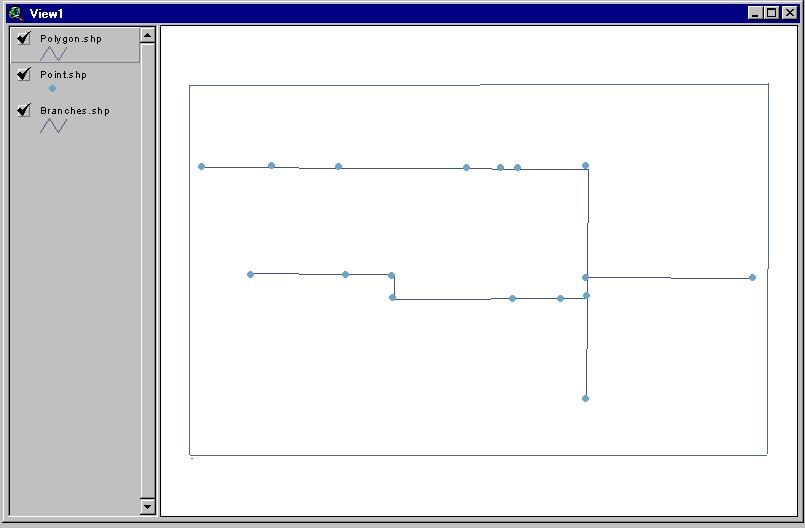
Let's view the polygons attribute table. Select the polygon theme in the view and click on the table icon. Your table should look something like this: 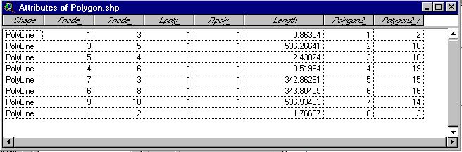
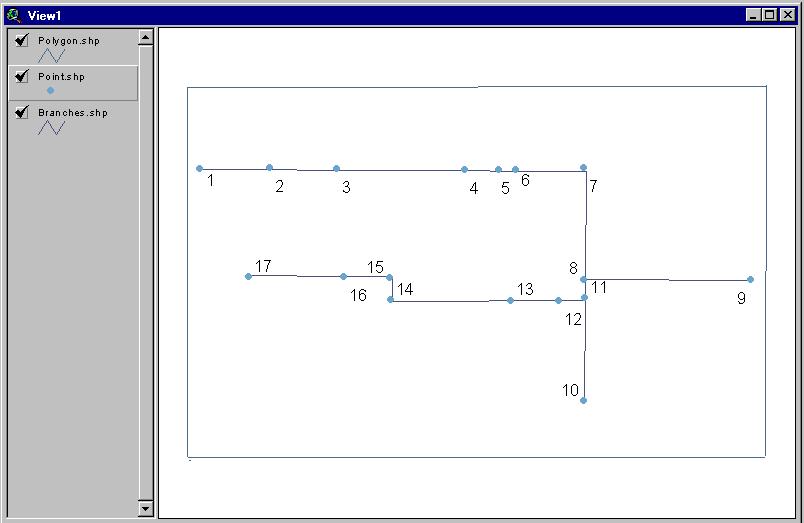
Now, let's display each nodes' id number. Highlight the nodes theme in the view and go under Theme / Properties . Under the "Label Filled" pull out menu, choose "Nodes_id".
Then, under the View menu, pull out the "Auto Label" menu, and select the " Find Best Label Placement"
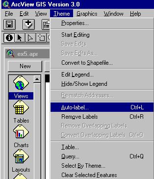

Now, your View should look like this: