
Geometric Design Lab - Lab 13
Design Project Part 4
Design the Freeway Exit Ramp of the Grade-Separated, Two-Quadrant, Partial Cloverleaf
A Interchange using GEOPAK
Copyright © 2009 by Dr. Thomas W. Rioux
Students taking this course may print one copy of this document for their
personal class use.
Objective: Design the Freeway Exit Ramp of the Grade-Separated,
Two-Quadrant, Partial Cloverleaf A Interchange using GEOPAK.
Activity: Start Windows Explorer and copy the file "Z:\MicroStation\job12.gpk" to "Z:\MicroStation\job13.gpk" and "Z:\MicroStation\lab_12.dgn" to "Z:\MicroStation\lab_13.dgn"; Start MicroStation and open the 2D design file "Z:\MicroStation\lab_13.dgn"; Start GEOPAK, set the standard GEOPAK user preferences for this class, and set the standard COGO preferences for this class; Open the GEOPAK Project named lab_13, set Job Number to 13, set Subject to "Design Project Part 4", and set Coordinate Geometry for Temporary Visualization; Using MicroStation, Copy Parallel the main arc from the Entrance Ramp centerline 70 feet to the west and change the Color to red and Level to Level 2; Using MicroStation, Place Active Cell named EXTRMP; Using MicroStation, draw a circular arc tangent to the exit ramp cell, group the exit ramp cell and the circular arc, position the grouped exit ramp cell and circular arc, draw a tangent line between the arcs, and extend the tangent line; Store points for the Exit Ramp centerline; Define the Exit Ramp spirals and curve; Create a chain for the Exit Ramp and draw and station the Exit Ramp chain; Clear Visualized Elements (Temporary) and Exit COGO; Fit View 1 and plot the drawing; Exit MicroStation; Write the name of your team members on the plot; Complete Design Project Design Questions section 4; and Reboot the computer.
Background: This laboratory comprises Design Project Part 4 - Design the Freeway Exit Ramp of the Grade-Separated, Two-Quadrant, Partial Cloverleaf A Interchange using GEOPAK (see Design Project). You will use the features of MicroStation and GEOPAK to design the horizontal alignment for the Exit Ramp from Road 2000 to the Freeway. For the design of the exit ramp, see the 2004 AASHTO Green Book, Chapter 10 Grade Separations and Interchanges, Single-Lane Free-Flow Terminals, Exits, Taper Type Exits, on pages 849-851; Exhibit 10-72, Exit Ramps-Single Lane, -A- Tapered Design - Tangent, on page 850; and Exhibit 10-73, Minimum Deceleration Lengths for Exit Terminals With Flat Grades of 2 Percent or Less, page 851. Also see the TxDOT Design Division Operations and Procedures Manual 3/2009, Figure 3-35 (US) Entrance/Exit Ramps For One-Way Frontage Roads, page 3-90; Figure 3-43, Typical Exit Ramps without Frontage Roads, page 3-98; and Figure 3-49, Lengths of Exit and Entrance Ramp Speed Change Lanes, page 3-105. AASHTO and TxDOT recommend that the vehicle diverge from the rightmost through lane of the freeway traveling at the freeway design speed to a point where the vehicle is effectively in its own lane (AASHTO and TxDOT recommends the point where the right edge of the tapered wedge is about 12 feet from the right edge of the through lane) then the vehicle may decelerate to the design speed of the exit ramp on a tangent section of required length and finally the vehicle may negotiate the exit ramp curve at the design speed of the exit ramp.
A. Start Windows Explorer and copy the file "Z:\MicroStation\job12.gpk" to "Z:\MicroStation\job13.gpk" and "Z:\MicroStation\lab_12.dgn" to "Z:\MicroStation\lab_13.dgn".
B. Start MicroStation and open the 2D design file "Z:\MicroStation\lab_13.dgn".
C. Start GEOPAK, set the standard GEOPAK user preferences for this class, and set the standard COGO preferences for this class.
D. Open the GEOPAK Project named lab_13, set Job Number to 13, set Subject to "Design Project Part 4", and set Coordinate Geometry for Temporary Visualization.
E. Using MicroStation, Copy Parallel the main arc from the Entrance Ramp centerline 70 feet to the west and change the Color to red and Level to Level 2.
F. Using MicroStation, Place Active Cell named EXTRMP at an Active Angle of 0 and Relative to Level 2 such that the west end (Point A) of the cell touches the right lane edge of the eastbound lanes of the Freeway (a red line). This exit ramp cell is composed of a circular arc with 3025 foot radius and 3.1859334418394 degree sweep angle followed by a 471.7948 foot tangent section. The 340 foot portion of the tangent section is the deceleration length and starts where the exit ramp is 12 feet from the freeway lane edge. These values are derived from the Texas Department of Transportation Design Division Roadway Design Manual 3/2009 Table 2-3 Horizontal Curvature of High-Speed Highways and Connecting Roadways with Superelevation on page 2-12 and Figure 3-43 (US) Typical Exit Ramps Without Frontage Roads on page 3-98. The information can also be found online at http://www.dot.state.tx.us then TxDOT Library then Online Manuals then Search then List all manuals alphabetically then Roadway Design Manual then 2 Basic Design Criteria then 4 Horizontal Alignment then Curve Radius and finally Table 2-3 and Roadway Design Manual then 3 New Location and Reconstruction (4R) Design Criteria then 6 Freeways then General Information and finally Figure 3-43 (US) Typical Exit Ramps Without Frontage Roads. The deceleration length information can be found in the Texas Department of Transportation Design Division Roadway Design Manual 3/2009 Figure 3-49 (US) Lengths of Exit and Entrance Ramp Speed Change Lanes on page 3-105. The information can also be found online at http://www.dot.state.tx.us then TxDOT Library then Online Manuals then Search then List all manuals alphabetically then Roadway Design Manual then 3 New Location and Reconstruction (4R) Design Criteria then 6 Freeways then General Information and finally Figure 3-49 (US) Lengths of Exit and Entrance Ramp Speed Change Lanes.
G. Using MicroStation, draw a circular arc tangent to the exit ramp cell, group the exit ramp cell and the circular arc, position the grouped exit ramp cell and circular arc, draw a tangent line between the arcs, and extend the tangent line.
G.1. Place a Circular Arc with Level of Level 2, Color of 3 (red), Style of 0 (solid), and Weight of 0; with Method of Start, Center; with radius of the value from Lab Assignment 11 Step C.1; with Sweep Angle of 100 degrees; and tangent to the southeastern tip of the exit ramp cell placed in Step F.
G.2. Group the exit ramp cell and the circular arc.
G.3. Move the grouped exit ramp cell and circular arc to a position that will (1) accommodate your curve, (2) allow adequate distance between the Entrance Ramp and the Exit Ramp, and (3) allow for a tangent section between the two arcs and their spirals as specified in the Design Project.
G.4. Place a Line with Level of Level 2, Color of 4 (yellow), Style of 0 (solid), and Weight of 0 tangent to the arc drawn in Step E and tangent to the arc drawn in Step G.1 (HINT: Use the Place Smart Line tool, snap tangent to the arc placed in step G.1, then snap tangent to the arc placed in step E).
G.5. Extend/Shorten the line drawn in Step G.4 down to the right lane edge of the Exit Ramp created in Lab Assignment 11 and extend/shorten the line drawn in Step G.4 up to the 471.7948 foot tangent section of the exit ramp cell placed in Step E (HINT: use the Extend Element to Intersection tool).
H. Store points for the Exit Ramp centerline.
H.1. Store Point 41 on the most southwest point on the right lane edge of the Exit Ramp created in Lab Assignment 11.
H.2. Store Point 42 on the southeastern end of the line placed in Step G.4 and extended/shortened in Step G.5.
H.3. Store point 43 on the northwestern end of the line placed in Step G.4 and extended/shortened in Step G.5.
H.4. Store point 44 on the eastern end of the 3025 foot circular arc from the exit ramp cell placed in Step F (Point B) (this point is also the western end of the 471.7948 foot tangent section line).
H.5. Store point 45 on the western end of the 3025 foot circular arc from the exit ramp cell placed in Step F (Point A).
I. Define the Exit Ramp spirals and curve.
I.1. Determine the desired spiral length. Refer to Exhibit 3-30 on page 177, Spiral Curve Transitions on pages 184-185, and Length of Spiral on pages 185-191 in the 2004 AASHTO Green Book. Use the total of the tangent runout plus superelevation runoff for the desired spiral length. Round the desired spiral length to the next highest 0.1 feet if necessary. The spiral lengths for the two curves may have different lengths.
I.2. Store a Spiral SCS with Spiral Name of EXTR1, Back Tangent with Point Back of 41 and PI Point of 42, Entry Length of the value from Step I.1, Radius of the value from Lab Assignment 11 Step C.1, Exit Length of the value from Step I.1, and Ahead Tangent with Point Ahead of 43. The Exit Ramp should not cross or touch the Entrance Ramp. Note the location of the end of Spiral EXTR1A.
I.3. Store a Spiral SCS with Spiral Name of EXTR2, Back Tangent with Point Back of 42 and PI Point of 43, Entry Length of the value from Step I.1, Radius of the value from Lab Assignment 11 Step C.1, Exit Length of the value from Step I.1, and Ahead Tangent with Point Ahead of 44. The Exit Ramp should not cross or touch the Entrance Ramp. Note the location of the start of Spiral EXTR2B and be sure that there is no overlap with the end of Spiral EXTR1A.
I.4. If Spiral EXTR1A overlaps Spiral EXTR2B, the tangent section length between the end of Spiral EXTR1A and the start of Spiral EXTR2B is NOT within the limits specified in the Design Project, Spiral EXTR1B starts before Point 41, or the PI for Spiral EXTR2A ends after the start of the 471.7948 foot tangent section of the exit ramp cell placed in Step F then repeat Steps G.3, G.4, G.5, H.2, H.3, H.4, H.5, I.2, and I.3 with redefine set on until everything is within the specified limits. (Hint: to move the grouped exit ramp cell and circular arc, use a precision key-in or axis lock)
I.5. Store a Curve By Endpoints with Name of EXTR3, PC Point Number of 44, PT Point Number of 45, Radius of 3025 feet, and Counterclockwise.
I.6. Set Level Display for Level 2 to off.
J. Create a chain for the Exit Ramp and draw and station the Exit Ramp chain.
J.1. Store chain EXTRMP starting at Station value determined in Lab Assignment 12 Step I.1 and using Point 41, Spiral EXTR1B, Curve EXTR1, Spiral EXTR1A, Spiral EXTR2B, Curve EXTR2, Spiral EXTR2A, and Curve EXTR3.
J.2. Draw and Station chain EXTRMP using Label Scale of 200 and the settings from previous labs. Move the stationing data near Point 41 so that it is visible.
J.3. Move the curve data and the station data so that it is visible.
K. Clear Visualized Elements (Temporary) and Exit COGO.
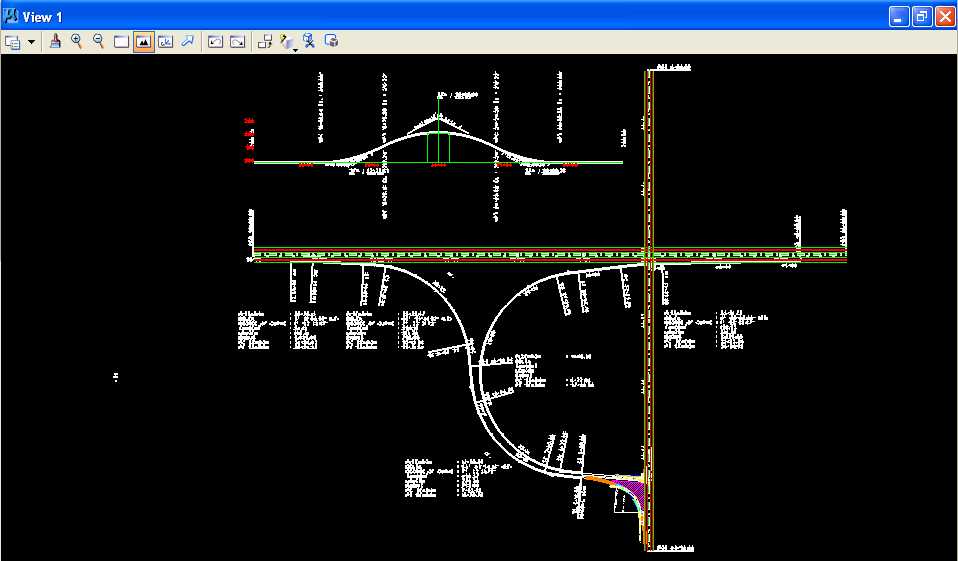
L. Fit View 1 and plot the drawing using ENGR-SC2-Laser-2 and options for View 1, Monochrome, Letter, Landscape, Maximize, and Settings -> Print Attributes -> Fence boundary off and Print border on.
Design the Freeway Exit Ramp of the Grade-Separated, Two-Quadrant, Partial Cloverleaf A Interchange using GEOPAK
M. Exit MicroStation.
N. Write the name of your team members on the plot.
O. Complete Design Project Design Questions section 4.
P. Reboot the computer.
Geometric Design Lab Spring 2011 web page
Latest Update: 11 Feb 2011 03:31 PM