Geometric Design Lab - Lab 10
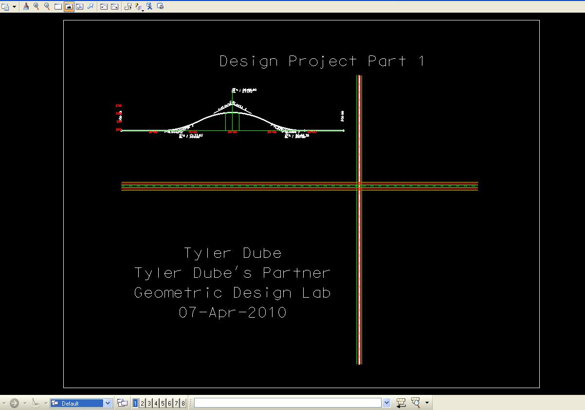
Design Project Part 1
Define the Vertical Alignment for Road 2000 over the Freeway using GEOPAK
Copyright © 2009 by Dr. Thomas W. Rioux
Students taking this course may print one copy of this document for their personal class
use.
Objective: Define the Vertical Alignment for Road 2000 over the Freeway using GEOPAK.
Activity: Copy the Design Project files to "Z:\MicroStation" ; Start MicroStation and create a 2D design file "Z:\MicroStation\lab_10.dgn" using the seed file "Z:\MicroStation\train2d.dgn"; Attach "design_project.dgn" and "design_project_part_1.dgn" to "Z:\MicroStation\lab_10.dgn" as Coincident reference files; Start GEOPAK, set the standard GEOPAK user preferences for this class, and set the standard COGO preferences for this class; Create a GEOPAK Project named lab_10; Store the points for the centerline of Road 2000; Store chain CHRD2000; Calculate the required grade to minimize the tangent grade distance between the ends of the sag and crest curves, length of crest curve, and length of sag curve for 50 miles/hr design speed; Define the vertical profile for Road 2000; Clear Visualized Elements (Temporary) and Exit COGO; Draw the vertical profile using the Design and Computation Manager; Fit View 1 and plot the drawing; Exit MicroStation; Write the name of your team members on the plot; Complete Design Project Design Questions section 1; and Reboot the computer.
Background: This laboratory comprises Design Project Part 1 - Define the Vertical Alignment for Road 2000 over the Freeway using GEOPAK (see Design Project). You will use the features of GEOPAK to design the vertical alignment for the centerline of Road 2000 which overpasses the Freeway. To provide adequate lateral and vertical clearance over the Freeway, the centerline profile of the finished grade (the bridge deck) on Road 2000 should pass through a point located 85 feet laterally from the centerline of the Freeway and 22.5 feet above the centerline elevation of the freeway. A design objective is to select a magnitude of gradient which will minimize the length of the tangent grade between the end of the sag and crest vertical curves while providing safe stopping sight distance at all points along the profile.
Design Questions: The file "Design Project Overview.doc" may be downloaded from \\disk.austin.utexas.edu\root\engrstu\class\caee\ce367.
A. Copy the Design Project files "design_project.dgn", "design_project.cel", "design_project_part_1.dgn", "design_project_plan_sheet.dgn", and "Design Project Overview.doc" from \\disk.austin.utexas.edu\root\engrstu\class\caee\ce367 to "Z:\MicroStation" .
B. Start MicroStation and create a 2D design file "Z:\MicroStation\lab_10.dgn" using the seed file "Z:\MicroStation\train2d.dgn".
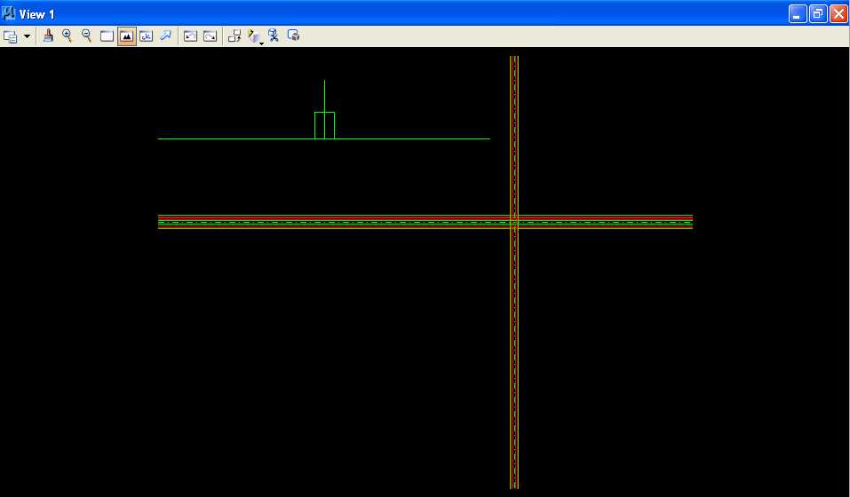
C. Attach "design_project.dgn" and "design_project_part_1.dgn" to "Z:\MicroStation\lab_10.dgn" as Coincident reference files at a scale of 1.0 to 1.0 and rotation of 0. In MicroStation Window 1, choose the Fit View icon. The 2 reference files should be visible. From the MicroStation dialog box, choose Settings -> Level -> Display. In the Level Display dialog box, choose design_project.dgn, set Level 4 for off, and close the Level Display dialog box. The "design_project_part_1.dgn" reference file is an aid to designing the vertical profile for Road 2000. This reference file contains a 2800 foot horizontal line that represents elevation 200 feet, a vertical line at the centerline of the 4-lane Freeway, and a rectangle centered about the centerline of the 4-lane Freeway that is 170 feet wide and 22.5 feet high at a 100:10 vertical scale.
D. Start GEOPAK, set the standard GEOPAK user preferences for this class, and set the standard COGO preferences for this class.
E. Create a GEOPAK Project named lab_10 using Job Number 10 with Subject of "Design Project Part 1" and set Coordinate Geometry for Temporary Visualization.
F. Store the points for the centerline of Road 2000 with Point 21 at the north end and Point 22 at the south end of the centerline (green dashed line). Calculate the station number for Point 21.
G. Store chain CHRD2000 starting at the station number for Point 21 calculated in Step F and using Point 21 and Point 22.
H. Calculate the required grade to minimize the tangent grade distance between the ends of the sag and crest curves, length of crest curve, and length of sag curve for 50 miles/hr design speed.

H.1. Use the above formulas to calculate G, L crest, and L sag using the design value for K crest from the 2004 AASHTO Green Book Exhibit 3-72 on page 272 for a design speed of 50 miles/hr, using the design value for K sag from the 2004 AASHTO Green Book Exhibit 3-75 on page 277 for a design speed of 50 miles/hr, and using W and H from the Design Project in feet.
H.2. Use the values of K crest, K sag, G, L crest, and L sag rounded to the nearest 2 decimals in the remaining steps.
I. Define the vertical profile for Road 2000.
I.1. Define the vertical profile using Layout Profiles (VPI Based) for Road 2000 using the settings from previous labs with Reference Station of the station number for Point 21 calculated in Step F, Reference Elevation of 200, and placed at the left end of the 2800 foot horizontal green line.
I.2. Set VPI 1 for the left end of the reference file design_project_part_1.dgn using the Reference Station and Reference Elevation, set VPI 2 for the left sag curve (Hint: subtract an additional 0.1 feet to account for rounding errors), set VPI 3 for the crest curve at the station where Road 2000 crossed the Freeway, set VPI 4 for the right sag curve (Hint: add an additional 0.1 feet to account for rounding errors), and set VPI 5 for the right end of the reference file design_project_part_1.dgn using the Reference Elevation.
I.3. Save Profile As PROFR2000.
I.4. In the Profile Generator dialog box, choose File -> K Value Table. In the K Values dialog box, choose File -> Open. In the K Value dialog box, choose KValues_2001english.kvl and press the OK push button. In the K Values dialog box, press the OK push button.
I.5. For VPI 2, VPI 3, and VPI 4, choose Symmetrical, set Speed to the design speed for Road 2000, and set K to the appropriate K value from Step H.1.
I.6. For VPI 3, set Station to Lock, press the Dynamic button, and move VPI 3 vertically until the profile clears the rectangle and there is no Overlap.
I.7. Save Profile As PROFR2000 and close the GEOPAK Profile Generator dialog box.
I.8. If there was an error saving the vertical profile, in the Coordinate Geometry Job:10 Operator: <your_2_initials> dialog box in the COGO Key-in field, enter make input file j10o<your_2_initials>.inp pro PROFR2000 and press the Enter key.
J. Clear Visualized Elements (Temporary) and Exit COGO.
K. Draw the vertical profile using the Design and Computation Manager for Job 10 using the settings from previous labs, use a Label Scale of 200, set DP Station to the station number for Point 21 calculated in Step F, set DP Elevation to 200, DP X and DP Y placed at the left end of the 2800 foot horizontal green line.
L. Fit View 1 and plot the drawing using ENGR-SC2-Laser-2 and options for View 1, Monochrome, Letter, Landscape, Maximize, and Settings -> Print Attributes -> Fence boundary off and Print border on.
Define the Vertical Alignment for Road 2000 over the Freeway using GEOPAK Plot
M. Exit MicroStation.
N. Write the name of your team members on the plot.
O. Complete Design Project Design Questions section 1.
P. Reboot the computer.
Geometric Design Lab Spring 2011 web page
Latest Update: 11 Feb 2011 03:31 PM