CE 319F LAB 4
There are two sets of conditions for the applicability of Bernoulli's equation. They are
| Set A | Set B |
| 1) the flow is steady, | 1) the flow is steady, |
| 2) the fluid is incompressible (i.e. density (r) is a constant), | 2) the fluid is incompressible (i.e. density (r) is a constant), and |
| 3) the equation is applied along a streamline, and | 3) the flow is irrotational. |
| 4) the effects of shear stress are negligible (i.e. negligible flow resistance). |
Conditions 1 and 2 are the same for both sets. For irrotational flows (Set B), Bernoulli's equation is applicable throughout the flow. For Set A, Bernoulli's equation can be applied along individual streamlines in the flow provided that the effects of shear are negligible.
Bernoulli's equation written using pressure and elevation heads is
 |
(4.1) |
where all of the terms are scalars and V = magnitude of the total velocity, i.e., components of velocity are not used in Bernoulli's equation. Using piezometric head, Bernoulli's equation can also be written as
 |
(4.2) |
When the conditions of Set A apply, the Bernoulli sum is constant along the streamline. When the conditions of Set B apply, then the Bernoulli sum (i.e., the sum of the terms in Bernoulli's equation) is constant throughout the region where the flow is irrotational. In some situations, Eq. 4.2 is preferred over Eq. 4.1 since Eq. 4.2 has only the velocity head and piezometric head in the Bernoulli sum. If the velocity increases, then the piezometric head must decreases regardless of any changes in elevation. Thus, a given change in velocity produces the same change in piezometric head regardless of the direction of flow (i.e., regardless of whether the flow is horizontal, vertically upward, vertically downward, or in any other direction).
Some of the heads used in fluid mechanics are shown in the table.
Head terms
Head |
Terms |
Grade line and position |
elevation head |
z |
centerline of pipe |
pressure head |
|
between centerline of pipe and HGL |
velocity head |
|
between EGL and HGL |
piezometric head |
|
HGL |
total head |
|
EGL |
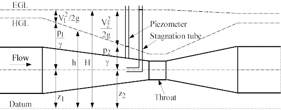
Since all of these heads have dimensions of length, they can be shown on a drawing or sketch (Fig. 4.1) that is drawn to correspond to physical dimensions. For flow in a pipe, z is usually taken to be the elevation of the centerline of the pipe. A hydraulic grade line (HGL) can be drawn to show the variation of the piezometric head. The distance from the centerline of the pipe to the HGL is the pressure head. An HGL above a pipe corresponds to positive pressure while an HGL below the centerline means that the pressure is negative. An energy grade line (EGL) shows the variation of the total head. Since the difference between the total head and the piezometric head is the velocity head, the distance between the EGL and the HGL is also the velocity head. (The flow disturbance and the internal shear in the expansion are large enough that Bernoulli's equation does not apply. The result is a decrease in the Bernoulli constant as the flow goes through the expansion. These effects will be discussed further in conjunction with the energy equation and flow in conduits.)

Schematic diagram (not to scale)
Fig. 4.1 - Experimental Apparatus to Illustrate Bernoulli's Equation and
Grade Lines
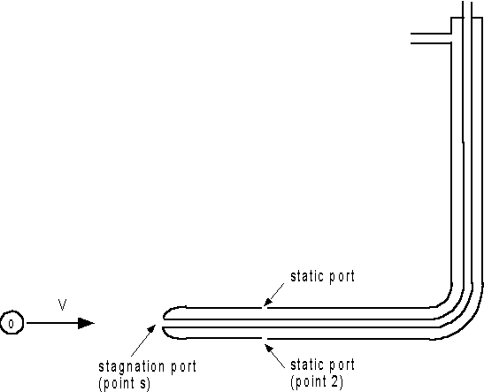
The first piece of apparatus is a Pitot tube, which is shown schematically in Fig. 4.2. A Pitot tube is two concentric tubes. The inner tube is open at the front of the Pitot tube. This opening is called the stagnation port; it measures the total head. The outer tube is the static tube, which has a few openings on the side of the Pitot tube to measure the static (or piezometric) head. Both the stagnation tube and static tube have tubing connections at the top of the Pitot tube. A differential manometer connected to the two tubing connections will measure the difference between the two heads, i.e., it will measure the velocity head, which is the difference between the total head and the piezometric head.

Fig. 4.2 - Schematic Diagram of a Pitot Tube (Not to Scale)
Applying Bernoulli's equation from point o in the approach flow to the stagnation point using the fact that Vs is zero at the stagnation point,
 |
(4.3) |
Thus, the difference in piezometric heads at points s and o is equal to the velocity head. However, the Pitot measure the difference in piezometric heads at points s and 2. As long the velocity going past point 2 is the same as the velocity at point o, then Bernoulli's equation shows that ho = h2 so that
 |
(4.4) |
The Bernoulli apparatus consists of a contraction, a straight section called the throat, and then an expansion back to the original pipe diameter. The contracting part gives a convenient method to demonstrate the application of Bernoulli's equation, provided that there is a very gradual taper. This is a very important condition. Attached to the apparatus are piezometers that can be used to measure the piezometric heads of the flow and a stagnation tube that can be used to measure the total head of the flow at different longitudinal locations within the tube.
 |
(4.5) |