CE 319F

Laboratory #8 - Head Losses in Pipe Flow

Objectives

The objectives for this laboratory are to see the effects of viscosity on low Reynolds number flows, to use a falling head viscometer to measure the viscosity of water, to observe that the head in a flow does not divide between flow paths when a flow splits, and to demonstrate and measure some of the types of head losses that occur in pipe flow.  This lab includes the evaluation of head loss due to shear on pipe walls and minor losses due to an elbow and due to a valve.

Theory

Energy Equation and the Concept of Heads

Assuming there is no shaft work or heat-transfer effects in a pipe system, the steady flow energy equation is
 
(1) 

where a1, a2 = kinetic energy correction factors, which are dimensionless; V1, V2 = the cross sectional average fluid velocities at points 1 and 2, respectively; g = acceleration due to gravity; p1, p2 = pressures at points 1 and 2, respectively; z1, z2 = elevations above the datum at points 1 and 2, respectively; hf = head loss due to boundary shear; and hL = minor losses.   This equation applies only for control volumes which are single streamtubes, i.e., control volumes with only one inflow and one outflow and with the inflow and outflow rates equal to each other.

Total head is defined as the rate at which kinetic and potential energy are transported by the flow plus the rate at which the fluid does work against the internal pressure, all divided by the rate at which the weight of the fluid is being transported by the flow.   That is,
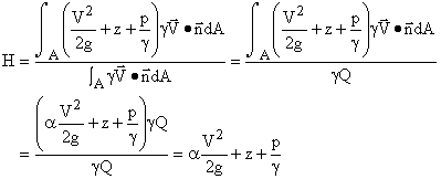
 
(2) 

There is a similar relationship for any head (h), i.e.,
 
h = P/gQ     or      P = gQh 
(3) 

where h can be the frictional head loss, the pressure head, the head from a pump, etc., and P is the rate of doing work (e.g., against shear stresses or pressure) or the power (e.g., from a pump) or the rate of transport of energy (e.g., the rate at which kinetic energy is transported by the fluid when the head is the velocity head).  All of the things that P can represent have dimensions of LF/T.  Since h is defined only for single streamtubes and since h is obtained by dividing P by gQ, head is like an intensity in that it is associated with each unit of fluid.  As a result, head is not divided between different flow paths when a flow splits nor is it additive when two or more flows come together.

Frictional Head Losses

Frictional head losses are losses due to shear stress on the pipe walls.  The general equation for head loss due to friction is the Darcy-Weisbach equation, which is
 
(4) 

where f = Darcy-Weisbach friction factor, L = length of pipe, D = pipe diameter, and V = cross sectional average flow velocity.  This equation is valid for pipes of any diameter and for both laminar and turbulent flows.  For laminar flow,
 
(5) 

where Re is the Reynold's number, which is defined for pipe flow as
 
(6) 

Substituting flam and Reynold's number into the Darcy-Weisbach equation yields
 
(7) 

For turbulent flow, the friction factor can be obtained from a Moody diagram or from the Colebrook-White equation, which is
 
(8) 

where ks is the equivalent sand roughness and ks/D is the relative roughness.  The values of  f  in the Moody diagram and in the Colebrook-White equation are empirical, i.e., they came from experiments.

Minor Losses

These losses, which are minor in magnitude for very long pipes but not necessarily for shorter pipes, are due to flow disturbance, frequently flow separation, for non-uniform flow.  The general equation for this type of head loss in pipes with the same diameter and velocity both upstream and downstream of the non-uniformity is
 
(9) 

where K is an empirical minor loss coefficient.  Some examples of minor losses are the losses due to a pipe entrance or exit; an expansion or contraction, either sudden or gradual; bends, elbows, tees, and other types of fittings; and valves, either totally open or partially closed.  For many situations with two pipe sizes (e.g., expansions and contractions), both the velocity in the smaller pipe is used in the text book for defining the minor loss coefficient.  Essentially all minor loss coefficients are empirical.  An exception to both the form of the minor loss equation and to the necessity of obtaining minor loss information from experiments is an abrupt expansion for which the momentum and energy equations can be used to get the loss as
 
(10) 

where Va is the velocity in the smaller pipe (i.e., the larger velocity) and Vb is the smaller velocity in the larger pipe.  A special case of an abrupt expansion is the exit from a pipe into a reservoir.  For this type of "expansion",  Vb = 0 in the reservoir so
 
(11) 

where V is the velocity in the pipe and K = 1.

Falling Head Viscometer

Subtituting V = Q/A into Eq. 7 and solving for Q, the result for a laminar flow can be written as
 
(12) 

For a tank and tube as shown in Fig. 1, hf,lam = h if the entrance loss and the velocity head at the downstream end of the tube are negligibly small.  Taking the tank as a control volume, the continuity equation gives
 
(13) 

Since the depth of liquid in the tank is h minus a constant (zb) and since there is only one outflow,
 
(14) 

Fig. 1 - Falling head viscometer

Substituting Eq. 12 for Q and separating variable, the result can be written as
 
(15) 

Integration with h = ho at t = 0 gives
 
(16) 

Measuring h as a function of time as a liquid drains from the tank and plotting h/ho on a semilogarithmic graph will produce a straight line when there is laminar flow in the tube.  The slope of that line will be f.    Determination of f will then allow m to be evaluated.
 Laboratory Equipment

Falling Head Viscometer

The tank for the falling head viscometer (Fig. 1) has a diameter of 15.16 cm (5 31/32 in.), giving AT = 180.5 cm2.  The 1/4-in. copper tube has an I.D. of 0.476 cm and a length of 1.842 m.

Branching Pipe

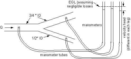
A branching pipe shown schematically in Fig. 2 is used to demonstrate the concept that head is not divided between different flow paths.  Each branch of the pipe is connected to a manometer.  The water levels in the manometer tubes show the piezometric head.

FigYbranch.jpg (16481 bytes)
Fig. 2 - Schematic diagram of branching pipes to illustrate that head is not divided between flow paths

Spiral Pipe

For determining the friction factor associated with shear resistance on pipe walls, a spiral copper tube will be used (Fig. 3).  The diameter (12.5 ft) of the spiral is large enough relative to the inside diameter of the tube (0.75 in.) that the flow in the pipe behaves essentially as it would for a straight pipe.  There are two manometer taps in the pipe.  The tubes are connected to a differential water-mercury manometer.  The pipe length between the two piezometer taps is 418 ft.  Higher flow rates have higher head losses and therefore larger diflections on the manometer.  The differential manometer gives the difference in piezometric head.  Since the pipe has a constant diameter, the velocity head is the same at the two piezometer locations, so the difference in piezometric head is also the difference in total head.  The grade lines are effectively as shown in Fig. 4.
 
SpiralPipe3.JPG (11381 bytes)
a) Photograph 

b) Schematic diagram 

Fig. 3 - Spiral pipe for measuring head loss due to boundary shear
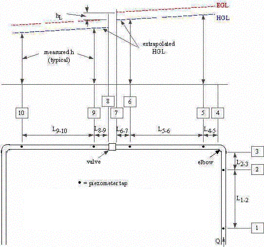


Fig. 4 - Definition sketch for heads in spiral pipe

PVC Pipe

For determining minor loss coefficients, there is a PVC pipe.  In one corner of the room, there is a 90o elbow.  Along the wall under the chalk board, there is a gate valve.  There are two piezometer taps upstream of the elbow, two between the elbow and the valve, and two downstream of the elbow.


L1-2 = 550.5 cm
L2-3 = 22.2 cm
L4-5 = 41.6 cm
L5-6 = 1116.3 cm
L6-7 = 20.6 cm
L8-9 = 36.7 cm
L9-10 = 551.5 cm
Fig. 5 - Schematic diagrams of PVC pipe for determining losses

Procedures

More details on the procedures tables for the data and calculations are given in the worksheet for this lab.

Falling Head Viscometer

  1. Fill the upstream tank with water.
  2. Open the valve and measure the depth of water in the tank as a function of time.
  3. Add the value of zb that the TA gives you to the measured depths to get h(t).
  4. Plot log(h/ho) vs. t and determine the slope (f) of the straight line portion.
  5. From the definition of f in Eq. 16, determine m.

Branching Pipe

  1. For the branching pipe, establish a flow in the pipe.
  2. Purge the manometer lines of air.
  3. Observe that the water levels in the manometer tubes are essentially the same (Fig. 1).
  4. Change the flow rate and again observe that the water levels in the manometer tubes are essentially the same.

Spiral Pipe

  1. For the spiral pipe, establish a flow rate in the pipe.
  2. Measure the flow rate volumetrically, i.e., measure the time (Dt) required to capture a given volume (D") of water and calculate the flow rate as Q = D"/Dt.
  3. Purge the manometer lines of air.
  4. Measure the change in piezometric head between the two manometer taps.  Remember that for a differential manometer with the manometer fluid being heavier than the flowing fluid in the pipe,
  5. (17) 

    where Dh = change in piezometric head, R = manometer reading, gm = specific weight of manometer fluid, and g = specific weight of flowing fluid.  Head losses are defined in terms of total head (H), not piezometric head (h), but the velocity head is constant for a constant diameter pipe, so Dh = DH.  The change in total head between the two piezometer taps is the head loss.

  6. Calculate f from
  7. (18) 

    using the measured head loss (hf = Dh), using the known values of L and D, and calculating V from Q and D.

  8. Calculate the Reynold's number from
  9. (19) 
  10. Plot f and Re on the Moody diagram.
  11. Determine the relative roughness of the pipe.

PVC Pipe

  1. For the PVC pipe, repeat steps (1) - (3) for the spiral pipe.
  2. Measure the piezometric head for each manometer tube.  The manometers for this pipe have water in them and all have the same pressure at the top, so the differences in the manometer readings directly give the change in piezometric head from one piezometer tap to the next.  This pipe is also a constant diameter, so changes in piezometric head directly give changes in total head.
  3. Calculate the head loss for the elbow and the valve.  To obtain these losses, it is necessary to extend the hydraulic grade lines from the locations of the manometer taps to the elbow and valve (Fig. 5).
  4. Calculate K for the elbow and valve from
  5. (20)